June Power June Power

How to Build a Resilient Power Supply for Critical Loads?

Time:2026-10-08 Author:Henry
0%

Critical facilities cannot treat electricity as a background service. Hospitals, data centers, laboratories, and emergency communication sites depend on stable power every minute. A brief voltage dip can interrupt ventilation, corrupt data, or stop a life-supporting process. The goal is not simply to add a larger generator. It is to design a coordinated system that manages failure before failure arrives.

To Build Resilient Power Supply for Critical Loads, engineers begin with a verified load inventory. They identify starting currents, harmonic distortion, thermal limits, and acceptable interruption times. A battery energy storage system may bridge the first seconds. An uninterruptible power supply can protect sensitive electronics. Automatic transfer equipment can shift selected circuits to standby generation. Each device needs proper coordination, physical separation, monitoring, and maintenance access. A locked cabinet is not a maintenance strategy.

Practical experience often reveals weaknesses that drawings miss. A generator may start successfully during a test, yet fail when fuel quality, cold weather, or battery aging changes the conditions. Operators should record transfer times, alarm histories, battery health, and load-bank results. They should also test realistic operating scenarios, including utility loss, equipment failure, and communications outages. No design is perfect. Some assumptions will be wrong. That is why independent reviews, manufacturer guidance, recognized engineering standards, and documented procedures matter. A resilient supply is built through disciplined analysis, careful installation, and repeated verification—not confidence alone. The strongest systems remain understandable under pressure, because technicians may need to make fast decisions beside humming equipment, flashing alarms, and limited information.
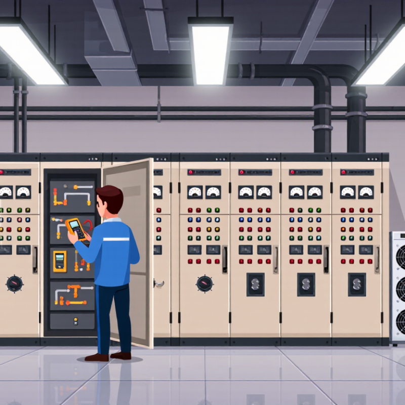
How to Build a Resilient Power Supply for Critical Loads?

Classify Critical Loads and Set Availability Targets, Including 99.982% Tier III

A resilient power system begins with load classification, not equipment selection. During a site walk-through, mark each circuit by consequence: life safety, mission-critical operation, or acceptable interruption. A ventilator, fire pump, and emergency lighting need different controls from office cooling or charging stations. Record starting current, runtime, transfer limits, and safe shutdown behavior. Do not classify every outlet as critical. That quickly makes the design expensive and less testable.

For a data room or industrial control area, a Tier III target means 99.982% availability, or roughly 1.6 hours of annual downtime. This figure comes from the Tier Standard: Topology report. It requires maintainable capacity, so planned maintenance should not interrupt the critical path. In practice, engineers often use N+1 UPS capacity, dual power paths, automatic transfer equipment, and tested standby generation. The weakest switching device can still defeat the whole target.

Availability must be measured, not assumed. The 2024 Annual Outage Analysis reported that 54% of surveyed outages exceeded $100,000 in cost, while 20% exceeded $1 million. That makes event logging, battery testing, fuel checks, and live transfer drills essential. A monthly inspection is useful, but not proof of resilience. One uncomfortable truth remains: a 99.982% target can hide unacceptable risk if a hospital control circuit shares a panel with noncritical loads. Review the classification after every process change. Human judgment is still imperfect.

Calculate Peak Demand, Inrush Current, and N+1 Capacity in kW and kVA

How to Build a Resilient Power Supply for Critical Loads?

Start with measured demand, not nameplate guesses. Record each critical load’s running kW, power factor, duty cycle, and operating schedule. Add simultaneous loads to estimate peak demand. For example, 72 kW at a 0.90 power factor requires about 80 kVA. Include battery chargers, cooling fans, controls, and future expansion. Small omissions can distort the result.

Inrush current needs separate attention. Motors, transformers, and switched-mode power supplies may draw several times their normal current. Identify which devices start together, then calculate the highest coincident inrush kVA. A short inrush event can trip protection, even when average kW looks acceptable. Use manufacturer data, field measurements, or a monitored startup test. Measurements beat assumptions.

Then apply N+1 capacity. If the critical load is 72 kW, three 40 kW modules provide 120 kW installed capacity. After one module fails, 80 kW remains, which supports the load with limited margin. Check kVA as well: a low power factor can overload equipment before its kW rating is reached. Allow practical headroom for temperature, aging, harmonics, and motor starts. My first calculation once ignored a cooling fan starting with the pumps. The result looked safe on paper, but the transient was not. Recheck the worst operating sequence, not only the average load.

How to Build a Resilient Power Supply for Critical Loads?

Peak demand, motor inrush, and N+1 capacity comparison for a representative critical-load system.

Assumptions: 75 kW connected load at 0.80 power factor, 62 kW coincident peak demand, and a motor-starting event that increases apparent power to approximately 162.5 kVA. The N+1 design uses three 40 kVA modules, providing 120 kVA installed capacity and 96 kW at 0.80 power factor while retaining one module as standby.

Design UPS Battery Systems to IEC 62040 Runtime and Safety Requirements

How to Build a Resilient Power Supply for Critical Loads?

A resilient UPS battery system starts with a measured load profile, not a hopeful estimate. Uptime Institute’s 2024 Annual Outage Analysis reported that power-related failures remain a major source of serious data-center incidents. The lesson is practical: define the critical load in watts, power factor, and starting current. Then select runtime for the actual emergency sequence. Five minutes may support a controlled shutdown. Thirty minutes may be necessary for generator startup and transfer delays. Do not confuse nominal capacity with usable capacity.

IEC 62040-1 addresses UPS safety, while IEC 62040-3 covers performance and test methods. These standards do not provide one universal runtime value. The designer must document operating conditions, battery autonomy, recharge behavior, protection, and abnormal-mode performance. Check end-of-discharge voltage carefully. Include battery aging, temperature correction, cable losses, and future load growth. A 20% design margin is common, but it is not a substitute for testing.

Safety details are physical. Provide insulated terminals, overcurrent protection, ventilation, thermal monitoring, and clear service isolation. Battery rooms need controlled access and visible emergency procedures. The Ponemon Institute has repeatedly linked outages with substantial financial losses, even when downtime is brief. Field testing should include a simulated utility failure, low-battery alarms, bypass operation, and restart behavior. A neat spreadsheet is not enough. I still prefer a witnessed discharge test, although real sites sometimes skip it because testing feels risky. That choice deserves review.

Provide NFPA 110 Type 10 Emergency Power Restoration Within 10 Seconds

How to Build a Resilient Power Supply for Critical Loads?

A resilient power supply must restore critical loads quickly and predictably. NFPA 110 Type 10 requires emergency power to become available within 10 seconds. That window starts after normal power failure detection. It is not a comfortable target. It demands coordinated equipment, controls, and maintenance.

Begin with a clear load schedule. Identify life-safety systems, fire pumps, medical equipment, communication systems, and essential ventilation. Use an automatic transfer switch with verified sensing and control logic. The generator must start reliably under cold, hot, and low-battery conditions. Fuel quality matters too. A full tank cannot compensate for blocked filters or weak batteries. Field reviews often find overlooked cable faults, delayed breaker operation, or poor ventilation. These small issues can consume several seconds.

Tips: Test the complete sequence, not just the generator. Record detection, cranking, voltage buildup, transfer, and load stabilization times. Test under realistic load conditions. Keep batteries charged, fuel tested, and spare parts available. Review alarms with facility staff, because confusing alerts can delay human response. Do not assume a successful monthly start proves Type 10 performance. It may not. A failed test should trigger investigation, documentation, and corrective work. Protect the system from flooding, extreme temperatures, unauthorized access, and routine construction changes. Resilience is built through disciplined verification, not equipment size alone.

Coordinate Protection, Maintenance Bypass, and Dual-Path Distribution Redundancy

A resilient power supply begins with coordinated protection, not simply larger equipment. Map the fault current at each panel, switchboard, and critical load. Set breakers to clear downstream faults before upstream devices trip. This preserves healthy circuits during a cable failure. Review these settings after every major expansion. Small changes can alter the entire protection study.

Maintenance bypass equipment should provide a controlled path around the power-conditioning system. Use mechanical and electrical interlocks to prevent unsafe switching. Label each position clearly. During a live-site inspection, technicians should verify voltage, phase rotation, and load transfer procedures. Practice under realistic conditions. A bypass that works only on paper is a serious weakness. I have seen teams overlook the neutral path during testing.

Dual-path distribution adds another layer of resilience. Feed critical equipment through independent A and B paths, with separate breakers, cables, panels, and physical routes. Do not place both paths in one crowded overhead tray. That creates hidden common-mode risk. Balance loads without making either path dependent on the other. Test one path offline while the remaining path carries the real load. Record temperatures, breaker status, transfer time, and alarm behavior. Recheck these results after maintenance. Redundancy is not absolute. Human switching errors, shared cooling, and incomplete records can still defeat a careful design.

How to Build a Resilient Power Supply for Critical Loads? - Coordinate Protection, Maintenance Bypass, and Dual-Path Distribution Redundancy

Design Dimension Recommended Design Practice Reference Data or Target Verification Method
Critical-load classification Separate life-safety, mission-critical, process-critical, and noncritical loads before selecting the power architecture. Document the required ride-through time, allowable interruption, maximum restart time, and load priority for each category. Approved load schedule, operating-risk review, and documented failure-mode analysis.
Capacity margin Size transformers, UPS modules, generators, switchboards, and feeders for the calculated demand plus future growth. Use a documented planning margin, commonly 15–25% for expected growth, while checking actual thermal and short-circuit limits. Load-flow study, measured demand profile, and equipment nameplate review.
Protection coordination Coordinate upstream and downstream protective devices so the nearest device clears a fault before upstream devices trip. Use time-current curves, instantaneous-trip settings, short-time delays, ground-fault settings, and manufacturer trip data. Signed coordination study covering normal, generator, bypass, and reduced-source operating modes.
Available fault current Confirm that every switchboard, panel, disconnect, transfer device, and protective device can withstand and interrupt the calculated fault current. Equipment interrupting rating and short-circuit withstand rating must meet or exceed the available fault current at the installation point. Short-circuit study, field verification of conductor lengths, and equipment rating audit.
Selective coordination under alternate power Recheck coordination when the source changes from utility power to generator, UPS bypass, or another alternate source. Generator fault current is often lower than utility fault current, which can change breaker operating times and coordination results. Separate operating-mode plots and functional testing of source-transfer sequences.
Continuous-load feeder sizing Size conductors and protective devices according to the applicable electrical code, ambient conditions, conductor grouping, voltage drop, and continuous-load requirements. In jurisdictions applying the common 125% continuous-load rule, verify that the feeder and overcurrent protection are rated accordingly. Conductor ampacity calculation, voltage-drop calculation, and installation inspection.
Maintenance bypass architecture Provide a bypass path that allows the UPS or power-conditioning equipment to be isolated for service while maintaining the critical load from an approved alternate source. Use mechanically or electrically interlocked switching to prevent unintended paralleling or incorrect source connection. Switching-sequence test, interlock inspection, and approved maintenance procedure.
Bypass transfer continuity Select break-before-make or closed-transition operation based on the load's interruption tolerance and the characteristics of the connected sources. Closed-transition operation requires compatible sources, synchronism controls, and protection against unintended source paralleling. Transfer test with representative load, waveform recording, and confirmation of voltage and frequency limits.
Neutral and grounding arrangement Define the system bonding point, neutral switching requirements, grounding electrode connections, and equipment grounding paths for each source and transfer mode. Four-pole switching may be required in some separately derived or switched-neutral arrangements; confirm with the governing code and engineered design. Grounding and bonding inspection, continuity testing, and neutral-to-ground voltage measurement.
Dual-path distribution Provide physically and electrically independent A and B paths from upstream sources to dual-corded critical equipment. Avoid shared breakers, shared panels, common bus sections, common cable routes, and single maintenance points unless specifically risk-assessed. One-line review, physical-route inspection, and single-fault simulation.
Single-corded critical equipment Use an approved static transfer switch, automatic transfer arrangement, or redundant power distribution device where equipment cannot accept two independent inputs. Confirm transfer time, short-circuit rating, compatibility with nonlinear loads, and maintenance-bypass provisions. Transfer-time measurement, load compatibility test, and failure-mode validation.
UPS ride-through capacity Set battery autonomy according to generator-start time, transfer sequence, load shutdown requirements, and operational risk. A 10–15 minute autonomy target is commonly used for many facilities, but the required value must come from the site-specific load and generator study. Battery discharge test, capacity trend analysis, and verification at the actual critical-load profile.
Generator integration Coordinate automatic transfer controls, generator loading, load-shed stages, retransfer delays, and UPS operating modes. Include motor-starting current, harmonic-producing loads, minimum generator loading, and generator transient response in the design review. Integrated black-start, load-step, transfer, retransfer, and load-shed testing.
Power-quality limits Monitor voltage, frequency, phase balance, harmonics, transients, and neutral current at the critical distribution points. Use equipment-specific limits and applicable power-quality guidance; investigate sustained voltage imbalance, excessive neutral current, or abnormal total harmonic distortion. Portable power-quality survey and permanently installed monitoring where risk justifies it.
Thermal and connection maintenance Inspect bus joints, cable terminations, breakers, bypass switches, batteries, ventilation paths, and enclosure conditions. Perform visual and torque inspections according to the equipment manual; use infrared scanning under representative load conditions. Inspection records, torque verification, infrared images, and corrective-action tracking.
Testing frequency Use a risk-based schedule that combines routine operational checks with periodic shutdown, transfer, protection, and battery tests. Review alarms and operating status routinely; perform detailed preventive maintenance at least annually or at the interval specified by the equipment and governing requirements. Maintenance calendar, test scripts, results, corrective actions, and management sign-off.
Failure-mode validation Demonstrate that a single breaker, feeder, UPS module, source, bypass component, cooling unit, or distribution path can fail without exceeding the critical-load interruption limit. Test planned maintenance, utility loss, generator start, UPS bypass, A-path loss, B-path loss, and recovery from abnormal conditions. Commissioning report, witnessed integrated-systems test, and updated emergency operating procedures.
Note: Reference values are planning ranges or commonly used engineering practices. Final ratings, protection settings, transfer arrangements, grounding methods, testing intervals, and code requirements must be confirmed through a site-specific engineering study and the applicable local regulations.

FAQS

How should I calculate peak electrical demand?

Measure each critical load’s running kW, power factor, duty cycle, and operating schedule. Add loads operating simultaneously. Include chargers, fans, controls, and future expansion. Nameplate estimates can mislead.

Why must I calculate both kW and kVA?

kW shows real power use. kVA reflects equipment loading. For example, 72 kW at 0.90 power factor requires about 80 kVA. Low power factor can overload equipment early.

What is inrush current?

Inrush is the temporary current surge during startup. Motors, transformers, and power supplies may draw several times their normal current. Short events can trip protection.

How can I estimate the worst startup condition?

Identify devices starting together. Calculate their highest combined inrush kVA. Use manufacturer data, field measurements, or a monitored startup test. Measurements beat assumptions.

How does N+1 capacity work?

N+1 means one extra capacity module supports the load after one module fails. Three 40 kW modules provide 120 kW installed. After one failure, 80 kW remains.

Is 80 kW remaining enough for a 72 kW load?

It may be enough, but the margin is limited. Check kVA, temperature, aging, harmonics, and motor starts. A cooling fan can change the result.

How should I choose UPS battery runtime?

Define the emergency sequence first. Five minutes may support controlled shutdown. Thirty minutes may cover startup and transfer delays. Use usable capacity, not nominal capacity.

What battery details deserve careful review?

Include aging, temperature, cable losses, end-of-discharge voltage, recharge behavior, and future load growth. A 20% margin helps. It cannot replace testing.

What physical safety features should a battery system include?

Provide insulated terminals, overcurrent protection, ventilation, thermal monitoring, and clear isolation points. Control access. Display emergency procedures visibly.

How can I verify emergency power restoration?

Test the complete sequence under realistic load. Record detection, cranking, voltage buildup, transfer, and stabilization times. Critical power should become available within ten seconds when required.

Does a successful monthly generator start prove reliable performance?

No. It may not. Test low-battery conditions, transfer controls, alarms, ventilation, fuel quality, and restart behavior. Review failed tests instead of hiding uncertainty.

Conclusion

Build Resilient Power Supply for Critical Loads by first identifying which systems require continuous operation and assigning clear availability targets, including a 99.982% Tier III objective where appropriate. This process should evaluate normal and emergency operating conditions, define acceptable downtime, and establish the level of redundancy needed for each load category.

The design must calculate peak demand, motor or equipment inrush current, and N+1 capacity in both kW and kVA to prevent overloads during startup or failure conditions. UPS battery systems should be selected and configured to meet IEC 62040 runtime, monitoring, and safety requirements. Emergency power should restore critical services within 10 seconds in accordance with NFPA 110 Type 10 expectations. Finally, coordinated protection settings, a properly rated maintenance bypass, and dual-path distribution help isolate faults, simplify maintenance, and preserve power availability without interrupting essential operations.

Henry

Henry

Henry is a dedicated marketing professional with a profound expertise in the company's offerings. With years of experience in the industry, he possesses an impressive understanding of the market dynamics and consumer behaviors that drive success. Henry is committed to sharing his insights through......